Calculate transmission lines and vias using professional-grade solutions
Extensive Library of Transmission Line Structures
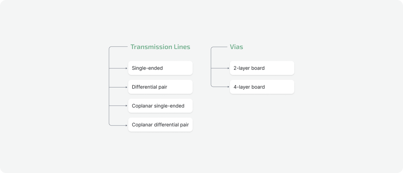
100+ ready-to-use transmission line structures (single-ended, differential pairs, coplanar) and vias which cover nearly all configurations in demand.Calculated Parameters
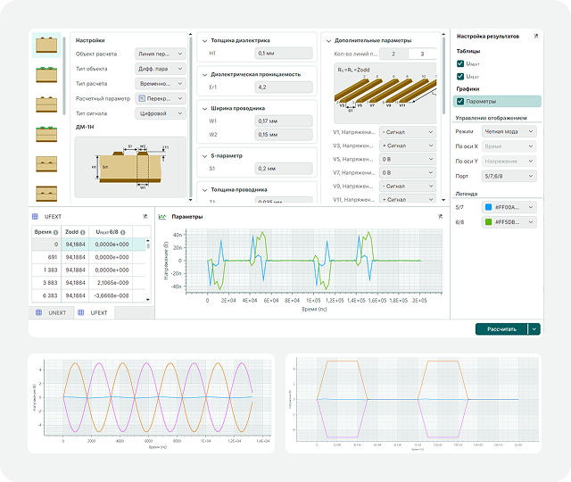
Calculation of transmission line parameters allows engineers to identify and resolve potential issues both before and during PCB design (RLCG parameters, Signal delay, Impedance, Signal attenuation, S-parameters, Crosstalk.Lossless Mode, Frequency & Time Domain Analysis
These analyses help you accurately determine the geometric parameters of PCB traces. You can calculate Reflected waves; Signal waveforms after passing through topological primitives; Signal attenuation and transmission parameters.Seamless Migration
Use your experience with Si9000 (Polar) or Z-planner (Z–Zero) to effortlessly move to SimPCB Lite. Our intuitive, lightweight interface requires zero learning curve.Integration with Your ECAD Software
Perform calculations in SimPCB Lite and then use the results in any PCB design ECAD system, including Altium Designer, Xpedition PCB, and PADS (Siemens).Cross-Platform Compatibility
SimPCB Lite is a universal solution that runs on both Windows и Linux.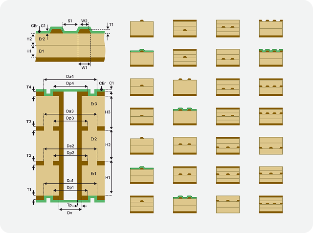
Transmission Line & Via Structures
SimPCB Lite ships with a large library of over 100 transmission line and via structures, most commonly used in PCB design. Using them, you can build practically any PCB circuit you need. Supported structures include:
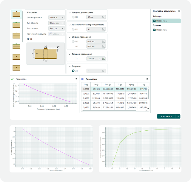
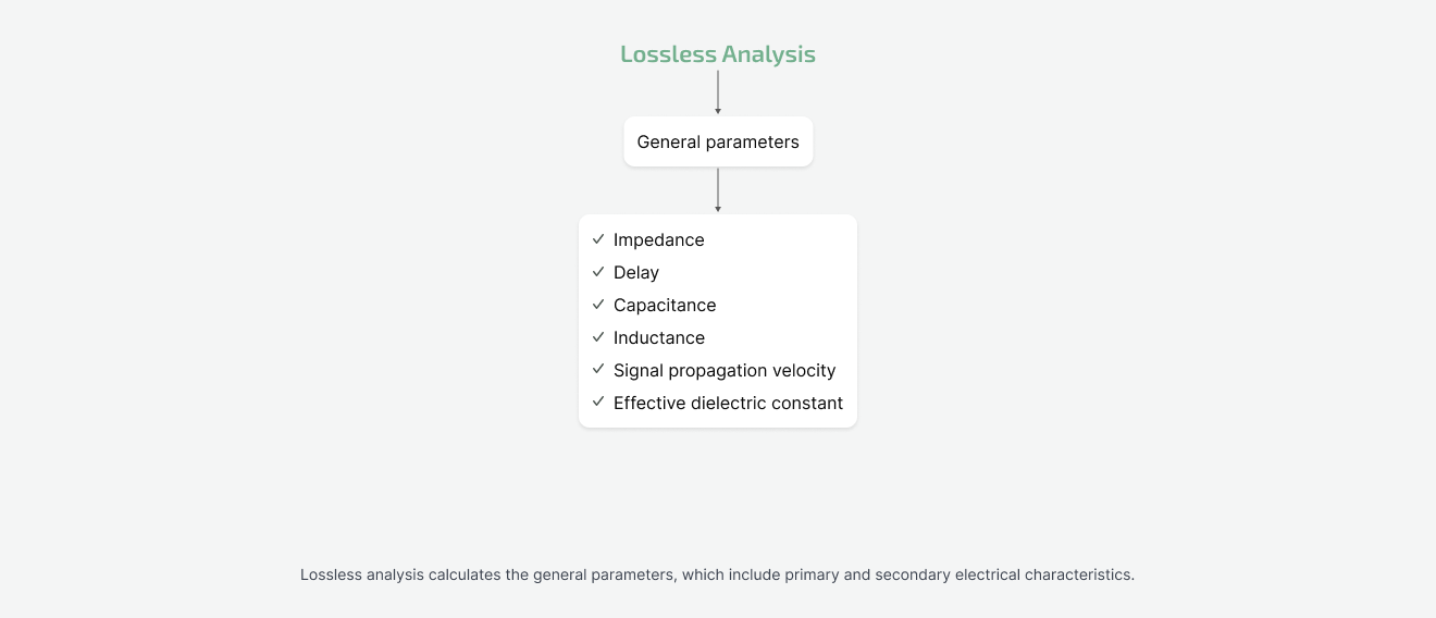
Lossless Calculations
A lossless calculation, performed without regard to frequency, is usually the first type of analysis an engineer runs. The transmission line model is represented by just two elements — capacitance and inductance. The lossless analysis is designed to calculate the primary and secondary parameters of transmission lines based on their geometric and electro-physical characteristics, and vice versa.
For more detailed analysis, you can specify a range of values for input parameters. The calculated data is then displayed in a table and on a graph.
Calculated parameters include:
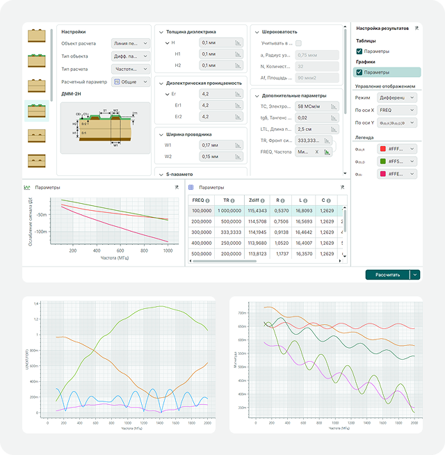
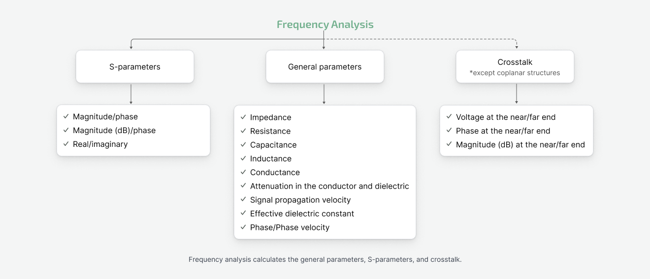
Frequency Analysis
Frequency analysis allows you to evaluate transmission line behavior at high frequencies. This calculation helps engineers identify and eliminate signal integrity issues such as attenuation, reflections, and crosstalk at an early stage in the design process. This is critical for maintaining the stability of modern high-speed digital interfaces and RF paths.
The frequency analysis and the decisions made based on it reduce the chance of errors and the number of iterations required during PCB design.
General parameters (including surface roughness):
S-parameters (including surface roughness):
Crosstalk:
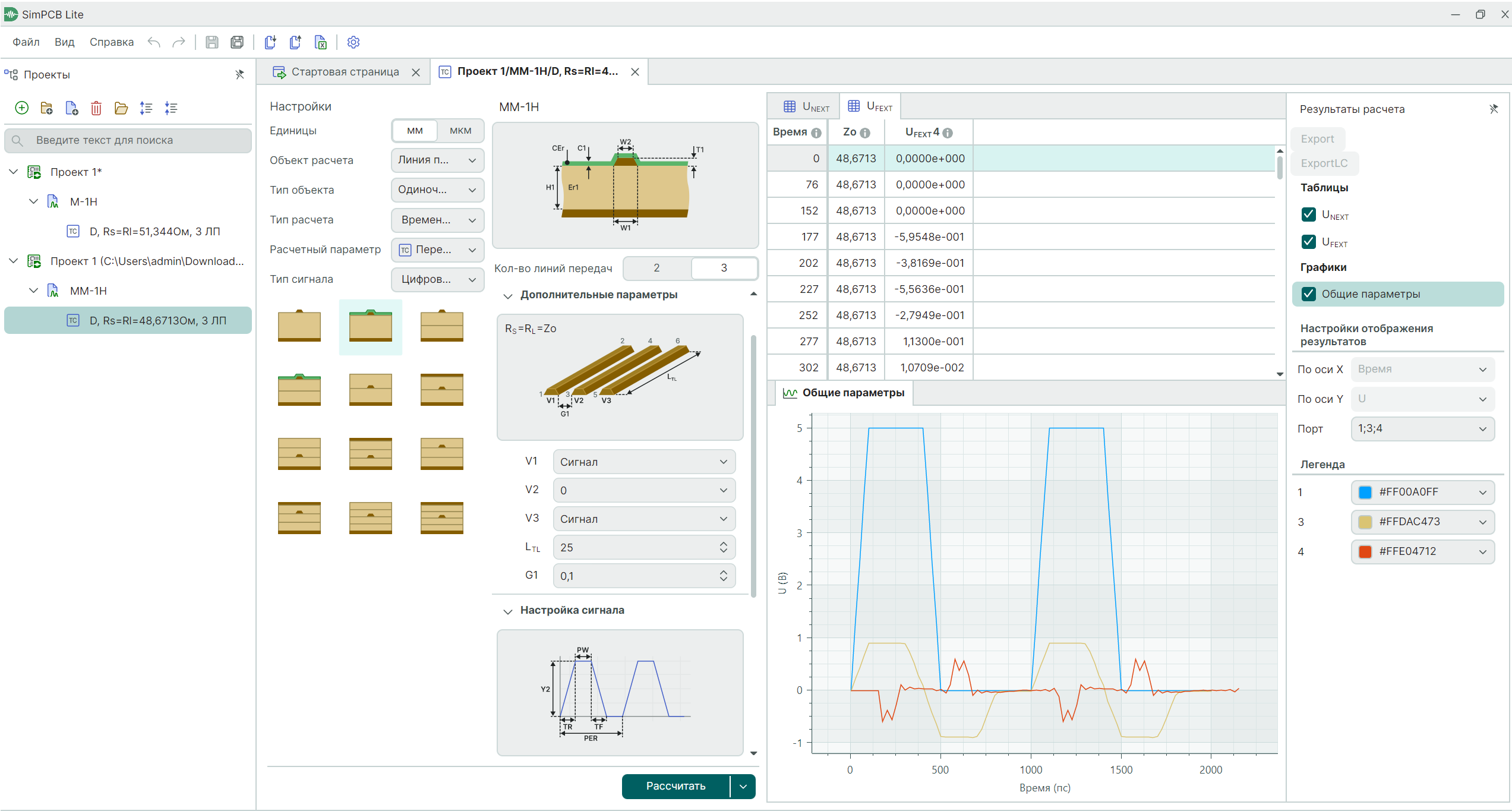
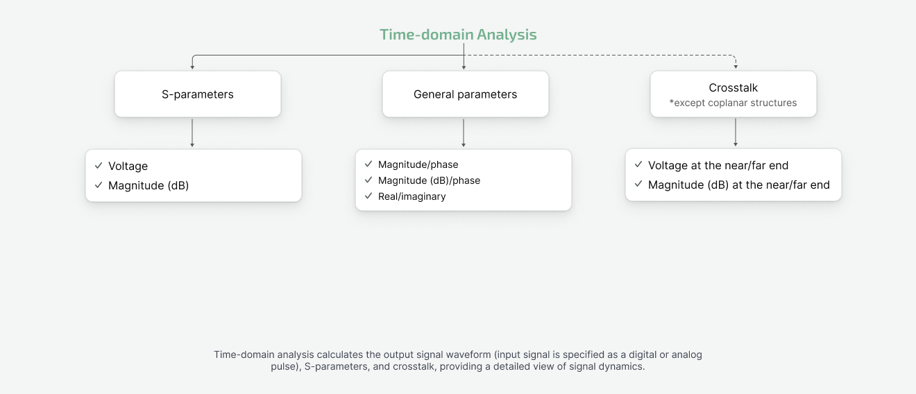
Time Domain Analysis
Time domain analysis allows you to simulate transient processes and evaluate the degradation of digital and analog signals after they pass through transmission lines.
You can analyze signal integrity, verify and monitor signal delay and rise time, and identify potential issues caused by pulse distortions.
Signal waveform calculation (including surface roughness):
S-parameters (including surface roughness):
Crosstalk:
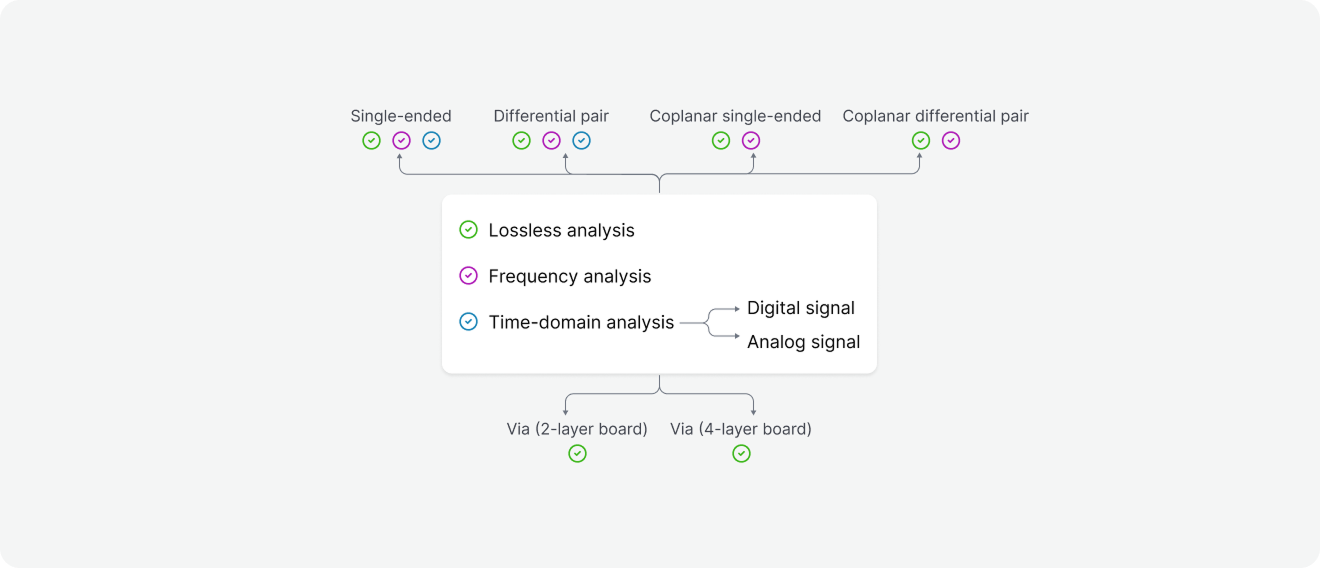
Transmission Line & Via Analysis Workflow
Frequenlty Asked Questions
How to buy the SimPCB Lite software?
1. Fill out the Order form.2. Confirm your agreement with the Public Offer, Privacy Policy and the terms of personal data processing.
3. Submit the Order form.
4. Within two working days we will send you an invoice for payment.
5. Once payment is confirmed, you will receive an email with a link to the download distribution and activation key.